Automatic Water Pump Controller Full Circuit Available Circuit Diagram And the Pump will stop when the water level touch the red wire. Circuit of Automatic Water Pump Switch. The circuit is very simple, You can easily make this project with some basic electronics components. You have to select the Relay as per the Pump voltage and current rating. Relay coil voltage: 12V DC Relay Contact Rating: As per the Pump rating Simple automatic water level controller circuit. See more: circuits for beginners. And this result to both transistors no conduction. So current through R5 and D1 to trigger base of Q3, cause Q3 conducts current to cause the transistor Q4 also works. When Q4 conducts current, LED1 will get a forward biased. So it glows.

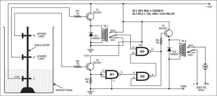
This simple, compact, and cost-effective design uses a Single NAND gate IC (CD4011) and operates on a 12V DC power supply, with minimal power consumption. The circuit can be divided into two main sections: - Advertisement - Automatic Water Pump Indicator Circuit Fig. 2: Automatic Water Pump Indicator Circuit

Automatic Water Pump Controller Circuit Circuit Diagram
The article portrays a basic and economical "automatic water pump controller" circuit. A "water pump controller" detects the level of water in a tank and drives the water pump. The controller controls the output and speed of the pump. The input factors are given by different sensors, for example, level sensors and flow meters. The automatic water pump circuit is a simple yet effective way to keep a water supply moving in a wide variety of applications. It works by automatically sensing when there is a lack of water in the system, and then triggers the pump to switch on and fill the supply back up. This ensures that your water always stays at the desired level, making
The following components are required to make the Automatic Water Pump Controller Circuit . S.no Component Value Qty; 1. Step-down transformer : 230V to 9/12V, 100mA-200mA: 1: 2. Clap switch circuits are simple circuits mostly used to fashion sound signals as electrical control signals. Electronics clap switches are used in places where
Automatic water level controller Circuit Diagram
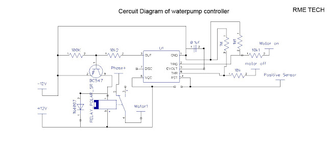
RL = Relay 12V 200E, > 5 AMP CONT ( According to pump HP) 2) IC 555 Based Automatic water Level Controller Circuit. The next design incorporates the versatile work horse IC 555 for implementing the intended water level control function in rather very simple and yet effective manner.

In this section, we talk about the circuit operation of an "automatic water pump controller". The circuit is utilizing just three segments which are a 2N4401 transistor, one 1.2K resistor, and one DPDT relay. There are three probes in the circuit which ought to be set in the water, and any thin wire will carry out the job. WITH AUTO SHUT DOWN WATER PUMP: it automatically shut downs water pump wen water tank is fullComponents RequiredPower supply (6v)NE 555 timer ICResistors (100Ωx2, 10kΩ)Relay (6V, 30A)BC 548 transistor x21N4007 Diode Automatic water level controller circuit is a simple engineering project. It can automatically switch ON and OFF the