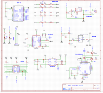
Build the talking ESP32 clock for the exact time Circuit Diagram An ESP32 based alarm clock. This is a bedside alarm clock and light controller I developed. IT relies on a number of external libraries: OpenWeather by Bodmer TFT_eSPI by Bodmer JSON_Decoder by Bodmer (Thanks Bodmer. This project would not be possible without you) ESP8266Audio by Earle F. Pillhower III NeoPixelBus by Makuna DS3232RTC by Jack
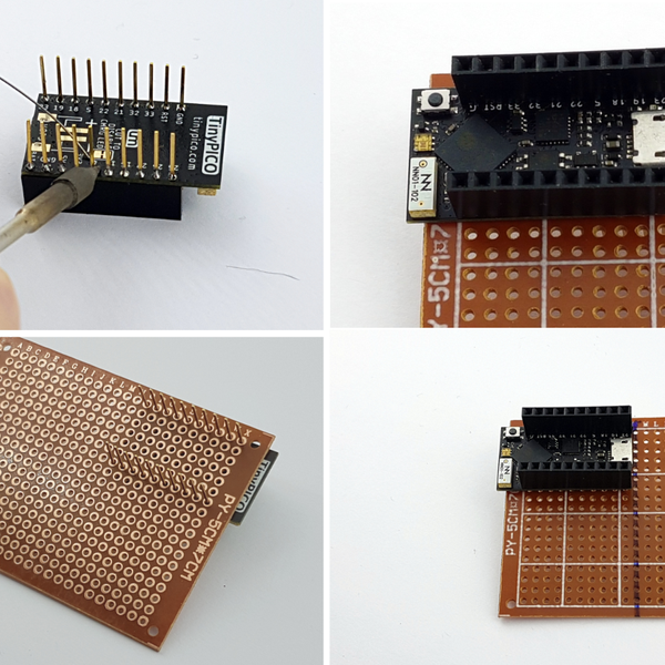
𝗧𝗘𝗖𝗛𝗗𝗲𝘀𝗶𝗴𝗻, most trusted electronics components marketplace: https://bit.ly/3Dli4w9𝗣𝗿𝗼𝗷𝗲𝗰𝘁 This open-source project demonstrates how to build a multifunctional smart alarm clock using ESP8266 or ESP32 microcontrollers, featuring a network interface, sunrise wake-up light, and temperature display. Based on your own hardware setup, you will need to search for @EB-setup comments in the code to adjust the hardware pins and other
DIY ESP32 Based Smart Clock with Weather Forecasting & Alarm System Circuit Diagram
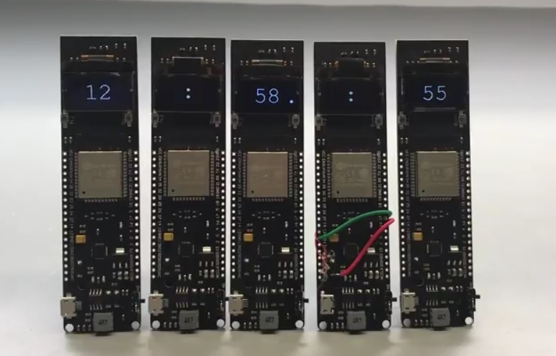
ESP32 based "Smart" alarm clock. Talking alarm clock with wake-up sequence (NeoPixel light animation, wake-up sounds, information like news, weather and personal calendar). Touch control. Internet radio. Sleep (activity) monitoring using radar for motion detection. Smart phone app for control and settings. OTA updating and remote console (telnet). Explore comprehensive documentation for the ESP32-Based Smart Alarm Clock with I2C LCD Display and Bluetooth Connectivity project, including components, wiring, and code. This circuit functions as a smart alarm clock utilizing an ESP32 microcontroller to interface with an I2C LCD display and a DS3231 real-time clock for accurate timekeeping. It features Bluetooth connectivity for potential
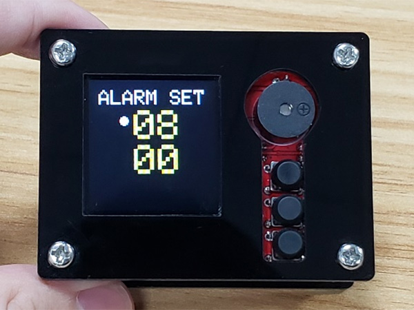
6.2.1 Clock After the WiFi setting or powering again, you will see the time shown on the display. The number in the bottom of right is the alarm time, and the point before the alarm time indicates that the alarm is activated. Press S3-button to disable the alarm. 6.2.2 Alarm Clock Press the S1-button to change the page to Alarm setting. The DS3231 can store up to two alarms: alarm 1 and alarm 2. These alarms can be configured to trigger based on a specific time and/or date. When an alarm is triggered, the SQW pin of the module outputs a LOW signal. You can detect this signal with the ESP32 and trigger interrupts, or even to wake it up from deep sleep. It parses the data (e.g., using JSON parsing libraries) to extract the relevant information (alarm time). ESP32 Takes Action: Based on the retrieved alarm time, the ESP32 can activate the LEDs (or speaker) at the designated time or perform other actions based on your programming (e.g., light up specific LEDs in a sequence).