DC Motor Control Using Single Switch Circuit Diagram In this video, I'll show you how to create a simple and efficient motor speed control circuit for DC motors ranging from 6V to 12V. Perfect for various DIY p As the name suggests, the purpose of the L293D motor driver is to drive DC motors. The L293D is a popular motor driver IC that has a built-in H-bridge circuit that can drive two DC motors simultaneously. It can supply up to 1A of current and voltages from 4.5V to 36V. This means the L293D motor driver is ideal for building multi-wheel robot

The next figure below shows a very simple DC motor speed controller circuit that employs a MOSFET as a high-power potentiometer (rheostat). The circuit is designed to work with 12 volt DC motors having a peak current usage of below 5 amp. This is a simple pulse width modulation speed controller for a DC motor which uses one of these, a 555 timer, and we're going to show you how the circuit works, how to design one and even turn it into a professional looking printed circuit board. Making a circuit to control a DC motor speed may look easy, but having a circuit which can provide enough torque to the motor even at lower speeds may not be so simple. In this post we discus how to build a simple DC motor speed controller circuit which can provide sufficient power or torque to the motor even at slower speeds.
Speed Controlling of DC Motor Using MOSFET Circuit Diagram
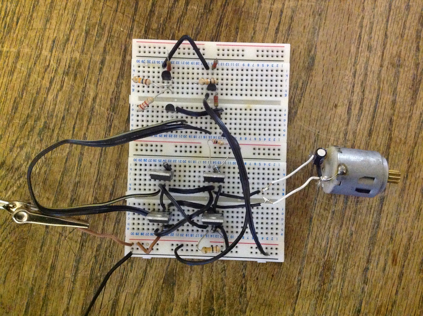
In this instructable, I'll demonstrate a simple and inexpensive circuit that controls a DC motor from two I/O pins. It requires no integrated circuits, and uses commonly available parts. I recommend you build it on a breadboard the first time. I designed this circuit, but I'm not the inventor of this type of motor controller.

Here's the simple circuit diagram for controlling a DC motor's speed using an Arduino and a MOSFET. This minimal-component design is easy to understand. For direction control, check out our L293D project. Circuit Diagram Overview: Components: Arduino UNO, MOSFET, 1k Ohm resistor, 10k Ohm potentiometer, diode, 12V power supply. Connections: Hello Guys today in this video I will show you How To Make Simple DC Motor Speed Controller Circuit Check the electronic components you need here: https://ww
