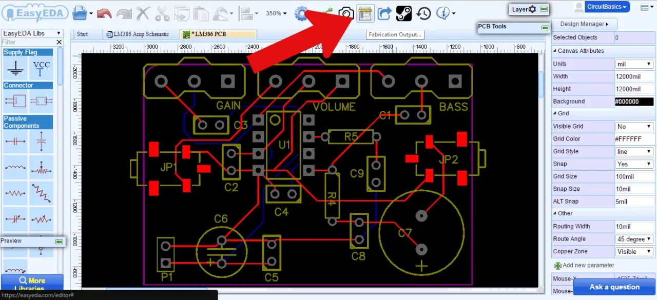
Electronic Circuit Board Design Circuit Diagram Printed Circuit Boards (PCBs) are crucial in today's electronics, connecting various components seamlessly. For beginners, designing a PCB can seem overwhelming; however, using a structured approach simplifies this task significantly. Start by clearly defining your circuit requirements and drafting a schematic to guide the design process. Your new project will be empty. It's now your job to first create a schematic, then later draw the board layout. You create the schematic from the Schematic Layout Editor, also called Eeschema. Open the editor by double-clicking on the schematic file on the left, or by clicking on the Schematic Layout Editor button (Image 2.2). You need to create a printed circuit board so you can see it in action! Whether your circuit is a project for school/college or is a final piece of electronics in a professional product for your company, implementing your circuit on a PCB will give it a much more professional appearance and give you an idea of how the finished product will look!

A Printed Circuit Board or PCB is one component that is present in almost all the electronic equipment we use in our daily life. It is used in relatively simple circuits like digital camera circuits, toy circuits, radio and stereo sets etc. is one of the web-based collaborative Electronic design automation(EDA) platform, owing to its

KICAD TUTORIAL Make Your First Printed Circuit Board Circuit Diagram
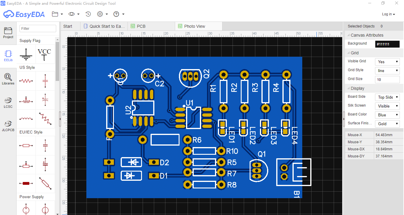
Usually, you start with a drawing of the circuit. Then you have to draw this circuit into a design tool, such as KiCad. Draw Circuit Board Layout. So, you have your schematics drawn in your design tool. Now you need to draw the circuit board. You need to draw the wires that connect the different components. Acquire a circuit board. Circuit boards are about a dollar apiece, and are simply a layer of copper over an insulator. The typical size is usually 3.5 inches (8.9 cm) by 5 inches (12.7 cm). Drawing is simple; all that is required is an indelible marker, such as a Sharpie. A ruler is also helpful. In this tutorial, we'll show all the steps involved in creating your circuits and schematics, then we'll transition into creating a circuit board design that can actually be manufactured. There is a lot that goes into any engineered circuit board design, from a basic printed circuit to a complex non rigid PCB. Any new electronic device will
Printed Circuit Boards (PCBs) are the backbone of all electronic devices. For beginners, students and professionals, learning PCB designing can be a highly rewarding skill. In this comprehensive step-by-step guide and tutorial, we will learn basics of PCB design, essential tools and Free software to begin with, and guide you through each step