RFID Access System Circuit Diagram Advantages of using RFID gate entry systems for residential HOA and commercial sites. Increased security: ANPR, or Automatic Number Plate Recognition system, is a type of vehicle access control that uses cameras to read license plates. When a vehicle approaches the gate, the ANPR system will take a picture of the license plate and compare Learn how to make Arduino RFID/NFC Door Lock system, how to use RFID/NFC tag to unlock the door, how to make a security door lock system, how to program Arduino step by step. The detailed instruction, code, wiring diagram, video tutorial, line-by-line code explanation are provided to help you quickly get started with Arduino. Find this and other Arduino tutorials on ArduinoGetStarted.com.

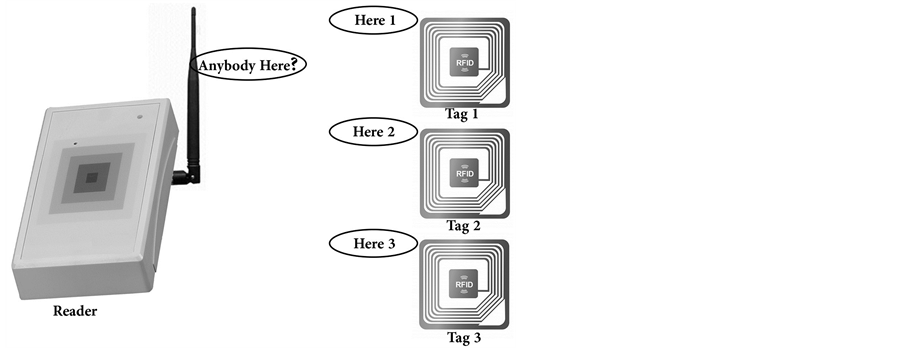
Long Range RFID Reader for Automated Vehicle Entry at Apartments Gate. When the Vehicle is in range, the RFID reader reads the RFID tag on the Vehicle Windscreen, and relays the information to Processing Unit/Controller. The Processing Unit checks the list of verified tags. Upon finding the particular RFID number on this authorised list

RFID Gate Entry Systems For Beginners Circuit Diagram
An RFID door lock system is an automated access control system that uses radio frequency identification (RFID) technology to identify and authenticate users. However, many other factors can affect the total cost of an RFID access system. Number of doors or entry points: The more entry points, the higher the cost. activities i.e. entry and exit. This is made possible by automatic synchronization of the system with a secured webpage via internet and offline system. Index Terms— Internet of Things (IoT); Arduino; RFID; door unlocking system; secure access; real time control INTRODUCTION We are living in 21st century the traditional system of Consequently, this studyproposed an automatic door lock system that will use a passive type of RFID technology. The proposed system is to secure space located on same or different part of buildings.

RFID stands for Radio Frequency Identification, a technology that enables communication between an RFID reader and an RFID tag using radio frequency signals.An RFID door lock system uses RFID technology for access control.. The RFID tag contains a microchip and an antenna. When the RFID tag is within the range of the RFID reader, the reader sends out a radio frequency signal that activates the How does an RFID access control system work? The working process of an RFID access control system is as follows: Signal transmission: When a user brings an RFID tag close to the access control reader, the reader sends a radio frequency signal to activate the nearby RFID tag. Information transmission: Upon receiving the signal, the RFID tag sends its unique identification information back to Hello guys, In this tutorial, I will show you how to make an RFID door lock access control system using Arduino. OK enjoy it now.Short and sweet tutorial.Onl
PDF Arduino Based Entrance Monitoring System Using Rfid and Real ... Circuit Diagram
Using an RFID access control and door lock system. Access control RFID locks and credentials are not only much harder to duplicate, intercept or otherwise breach than a traditional key-based security system, these devices also provide a level of convenience to users that is rarely matched by any other alternative building security system.. Once a set of RFID credentials has been issued to a