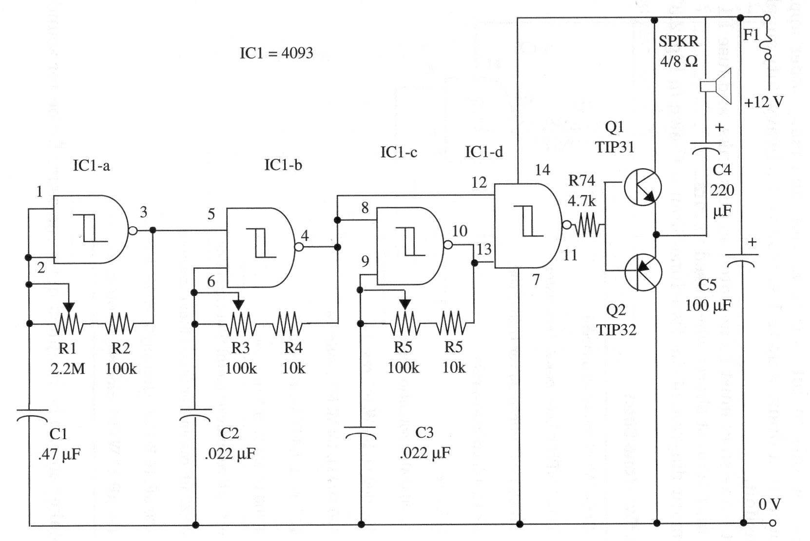
Simple Sirens Circuits Examples Circuit Diagram With SW1 positioned as shown in the circuit diagram it reproduces the typical dual tone sound of Police or Fire-brigade cars, by the oscillation of IC1A and IC1B gates. With SW1 in the other position, the old siren sound increasing in frequency and then slowly decreasing is reproduced, by pushing on P1 that starts oscillation in IC1C and IC1D.
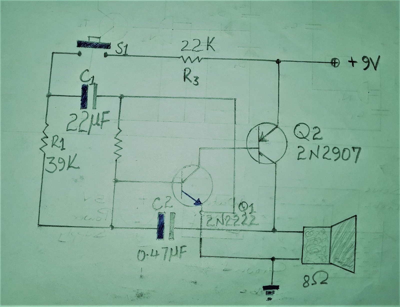
The second unit is an oscillator section. The condenser connected at the output is the feed back condenser. It determines the tone of the siren. Higher the value of the condenser the lower is the pitch. for high pitch sound (generally used in siren) feed-back condenser ranging from 0.047 uf to 0.1 mfd should be selected.
Building a Siren with Two NE555 Timers Circuit Diagram
A dual-tone siren is a circuit that amplifies an alarm sound and switches between two distinct tones. It creates an alternating sound effect similar to a siren. I can also design customized circuit diagrams as required by the users. If you have any questions related to this field, please do not hesitate to drop a comment! I am always here This electronic siren gives out a constantly shifting high abundancy sound. Since the supply voltage is not basic, it can be utilized as a part of autos, engine cycles or at home. It can supplant the conventional call chime. - . The circuit comprises of two different free running multivibrator and an oscillator. A circuit for a Two Tone Siren Sound effect, from a design by Radiofun232. https://www.youtube.com/watch?v=7ZaiqvRzKZQMany siren sound types can be made fro
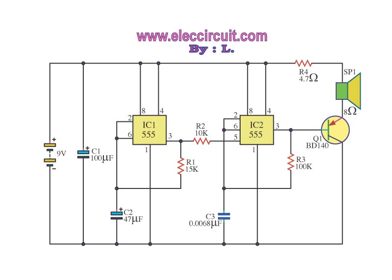
Using two NE555 timers—one for generating a low-frequency modulation signal and the other for producing an audible tone—you can create a siren circuit with a sweeping frequency effect. This project is an excellent way to explore the versatility of the NE555 and the principles of frequency modulation. Dual NE555 Setup: NE555 #1 (LFO
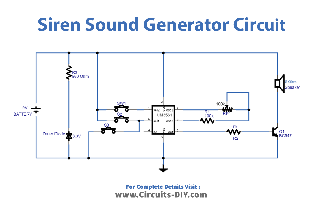
Simple Electronic Siren Circuits Circuit Diagram
The components used in this dual tone siren circuit result in a square wave output and the time constant selected is so as to give a fairly good rise and fall of the siren. However, one may change the value of coupling capacitors to get any other desired time constant. D = (T high / T) * 100; D = (0.0007623 / 0.0014553) * 100; D = 52.37%; The duty cycle is approximately 52%. 2) Pulsed IC 555 Alarm Circuit. The previous 800 Hz monotone alarm could be converted into a more interesting pulsed 800 Hz alarm by adding another astable multivibrator with the tone generator circuit as shown in the second concept below.. We have already studied how pin 5 can be used