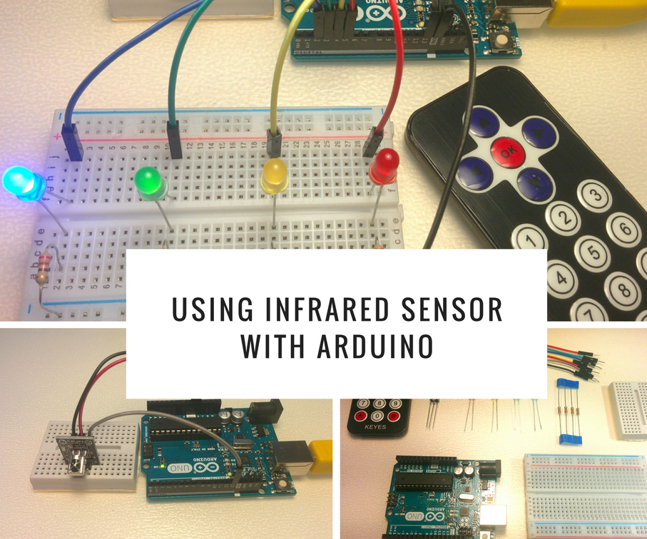
Using Infrared Sensor With Arduino 8 Steps with Pictures Circuit Diagram Here you can find a wide variety of IR phototransistors at Jameco.. The circuit we will build from these parts is: IR Detector Circuit. This circuit is very simple. When the IR phototransistor isn't exposed to any infrared light, there can be no current flow through the transistor, because infrared light is what produces base current in the transistor.
This project demonstrates how to create a basic circuit using an IR sensor, buzzer, and LiPo battery, with no Arduino involved. The IR sensor triggers the bu
How to Build an Infrared (IR) Detector Circuit Circuit Diagram
The circuit diagram : Infrared sensor circuit is very simple and straight forward. Circuit is divided into two sections. IR TX and IR RX are to be soldered on small general purpose Grid PCB. From this module, take out 3 wires of sufficiently long length (say 1 ft). Then, as shown above, connect them to VCC, preset and to ground on main board.

The first IR circuit will just show how the pair (IR LED & Photodiode) works. By using a transistor, we can arbitrarily amplify the analogue signal from the photodiode to power the LED. The circuit is very simple, all it needs is: Resistor: 2x 220ohm (or similar), 1x 10k. Diode: 1x IR LED, 1x Generic LED, 1x Photodiode
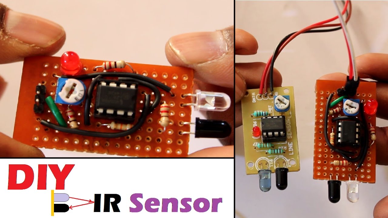
How to Make a IR Proximity Sensor at Home Circuit Diagram
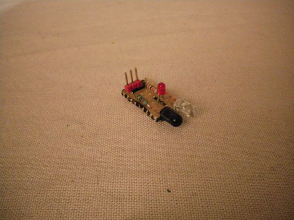
DIY - IR Module: A sensor is a device that detects and responds to inputs from the physical environment. The input can be light, heat, motion, moisture, pressure, or any other environmental phenomena. an IR Module is a combination of a IR transmitter and receiver circuit. Infrared light emitted by the IR LED is detected by the Photodiode // Simple Proximity Sensor using Infrared // Description: Measure the distance to an obstacle using infrared light emitted by IR LED and // read the value with a IR photodiode. The accuracy is not perfect, but works great // with minor projects. // Author: Ricardo Ouvina // Date: 01/10/2012 // Version: 1.0
